21.3.12

HYBrid BIOStructures: The Final Post.


With this post we mark the end of what we beleive is an insightful research on the topic of flexible formwork in concrete construction. We hope this body of work will be beneficial to the students of Emergent Technologies and Design and the students of the Architectural Association school of architecture for years to come.

We would like to acknowledge our tutors Michael Weinstock and George Jeronimidis for their continuos  support and their genuine interest in the development of this research. 

We would like to also thank all the people from different disciplines that supported our research with materials, information or by simply following our updates.

Please stay tuned to some changes in the blog, we would like to turn it around to record the professional research-based work we will be doing in the following years.

Best;

Riyad+Jack

10.2.12

Building Generation Final Views


 An aerial view of the resultant design. The image indicates the orientation of forms which are optimised for reducing the wind loads and for improving the stack ventilation. The fluidity in the exterior geometry is also visible.


A perspective showing the entrance on the centre. The building takes form according the forces that shaped it and act upon it. It is morphed as an extension of its surroundings and interacts with its immediate environment.


Close-up of the light effect on the floor created by a light well. The view also reveals the coherence in circulation between programs with different floor levels interconnected by one smooth surface which is within the accessible slope ratio.


As we near the end of the process examined within this research, a clear layout of the main intentions, the process and the outcome of that process is set out and illustrated. The main intention of this body of work is to reduce the complication that surrounds the construction of fluid concrete spaces. These spaces allow for coherence within the built environment enclosures. Throughout the course of research, a lot of challenges have been met due to the experimental nature of the investigation as a material process.  The challenges met have opened doors of perception to steer the interest towards areas of interest that branch out to investigate in detail some aspects that push for the main intention.

Our process of exploration has relied on a nonlinear synthesis between information gathered from models of different scales and mediums. Different weights of emphasis have been placed on parts of the process depending on the gain and relevance of the part under examination. The sequence of progression towards a viable solution to the proposed problem is recursive, and iterates between what these techniques have as results, of data to inform the research.

Complex Euclidian forms are not new in the design of contemporary buildings. Many architects have attempted the creation coherent forms that imitate the organic forms found in nature. As a departure from the rigid orthogonal planning of the human interventions on nature of its different scales; architects, planners and engineers have been adopting these complex geometries to create human built environments that take shape according the forces that act upon them. The immense and exponential advances in digital design, analysis and computation noticed in the recent years have allowed for these projects to become feasible. Advances in material sciences and the building industry have allowed for their construction.

The formation processes of these buildings have not yet reached a level of maturity to rival nature’s simplicity and economy in creating complex materialization. The process of construction is usually an afterthought of the envisioned design, where plenty of materials could be wasted in the process, leading to an un-ecological intervention with nature. 

We aimed for the resulting spaces of our work to stay truthful to the ambitions of unifying the building into a single system that handles environmental, pragmatic and structural conditions within its enclosure. 

7.2.12

Advancing Complex Concrete Construction Methods

Concrete as a building material has been used in a range of casting methods due to the variety of ways of working with the material. An array of application methods in the construction industry has been observed through the course of this research ranging from the traditional practice in third world countries to more up-to-date digital fabrication methods in workshops and research circles. 

Disadvantages are noted on both ends of the spectrum. The gains of using certain methods of casting concrete are considered as the key factor of choosing the correct construction logistics. These gains are measured by first calibrating the design outcome. The construction industry is surrounded by a set of restraints, which could influence deriving to logical solution for constructing a certain space within available resources, time constraints and expertise in advanced construction.

Complex geometric solutions that often lead to fluid spatial design are hence burdened by the constraints of place, time and resources. This could potentially lead to the risk of the monopolization of novelty in the built environment due to the lack of precision, know-how and advanced tools in unspecialized environments. 

The few architectural masterpieces that have over come the many difficulties of design and construction have often required unreasonable amounts of resources, materials and expertise. The results are spectacular environments, which hide behind ugly and excessive processes of formation. The complication and abundance of these processes, that often are an afterthought of the design process, habitually compromise the initial ideas imagined by the architect by untruthfully forcing materials into the complex geometries conceived earlier. 

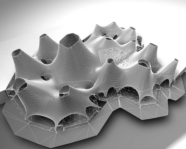
In order to achieve simplicity and truth in the process of constructing the spatial fluidity that we pursue in the course of this research, the process had to be inverted. The research aims at new construction method where materials assemble to perceived and controlled complex geometries, according to a design system that is the result of a thorough investigation of how these construction materials behave. 

The design system generates digital outcomes that are based on limitations and possibilities of the material system investigations presented earlier. 


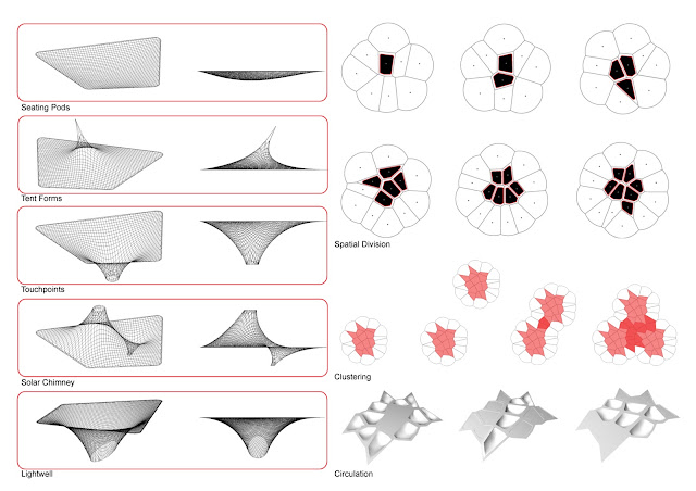
Following through with the design evaluation, the presented series of diagrams explain the construction process through a 4- step summary of the procedures. The geometries of the iteration generated previously, aid in envisioning the construction logistics at full scale. The intention of these illustrations is to provide a simplified outline of the possible set of instructions to carry out the construction procedure.

The process starts by excavating the ground according to dimensions provided by the generated plan. Starting wit the outlines of that plot, the topography levels are achieved by excavating different areas at different rates. Further excavation can be done on the areas where the private recessed sub programs have to be introduced. The outcome is a topography that has differentiation in the levels according to the programmatic zoning rules.


To achieve the conical tent forms, industry standard hydraulic jacks are introduced at the centres of the polygons of the designated program areas. The equipment investigated to raise the fabric upwards should have the capacity to retract its height, to facilitate the movement underneath the structure as its being tensioned, and the removal of this equipment after casting. The possibility of creating specific equipment is a possible solution to tension and retract as well as spray compressive material. Such innovation in the construction procedure departs from standard methods and is relevant to the envisioned material system.


The fabric tensioning process ends with the formation of a tensile membrane enclosure, which is dependent on construction equipment for support. As discussed in previous chapters, the material system requires the stiffening of that membrane with compressive material layering, which enables the free form structure to become a structural shell. The layering process is an integral part of reaching the ultimate aim of a coherent systematic approach to spatial forming. The materials researched previously pertain different characteristics, and have to be dealt with in specific techniques to achieve a desirable result.


The construction process comes closer to completion by making sure that the roof form is covered with enough thickness of material to guarantee its handling of compressive forces, and aim at distributing these forces almost equally across the free form geometry. The last step of the sequence is to apply shot-crete that is reinforced with barchip fibre onto a steel mesh applied on the hardened Jesmonite and quad axial fibreglass mesh layers. 

25.1.12

Design Proposal/ Digital Tooling System


A pseudo code for the final design proposal was written in the form of a flowchart. To enable the application of the material system on different sites and conditions, digital models have to be simulated for testing purposes. A digital algorithm that allows for recursion is needed to produce different iterations to constantly re-evaluate the generated outcome. Within the intelligence algorithm the material behaviour of the system and the possible spatial limitations have to be taken
into consideration.

Since fluidity of the transition between static architectural elements is the main objective, the
function of these spatial conditions has to be considered in the pseudo code of the design process. The values of areas of space to satisfy certain program are the main initial input.

The performative function of the architectural elements to be introduced, as realized by the previous
material investigation can be quantified and fine-tuned to modulate the thermal comfort within the interior spaces. This optimization process could also benefit from the recursive nature of the architectural parametric tool. The intention is a digital tool where the input is program areas and the outcome is fabric patches that could be materialized using digital fabrication tools. This could aid in bridging the gap between the designer and the construction worker to minimize error in the construction of complex concrete structures, and thus simplifying the process of forming and materializing such buildings.  


For a better resolution of the video please see the Vimeo link: http://vimeo.com/35645176

After writing the algorithm that incorporates the main plan generation of the proposed building, the extraction of restrain points from that plan, and the dynamic relaxation script of the roof shell, the algorithm is started to generate an initial iteration. Starting with the site, a topography that corresponds to the programmatic organization scheme is introduced. Pathways that are also the result of the circle packing and Voronoi generation of the plan are mapped onto the surface of the topography.

The centers of the polygons of the main program areas is also extracted to mark starting points of the solar chimney vectors. The vectors are tilted towards the leeward wind direction and away from direct solar radiation. Those instructions are carried forth according to environmental pressures of the immediate site and the spatial needs of each program under each solar chimney. The heights of the vectors are the result of the previous extraction of the height to area ratios of the conical form of each program, as explained earlier.

The interesting part of working with the digital mesh relaxation algorithm is its capacity to be morphed using similar methods of forming as the physical fabric to achieve similar tensile formations. The mesh is cropped for holes digitally, and restraint points are marked corresponding to these openings to create the architectural elements investigated earlier. Restraint points are also marked around the edges to create arch-like openings to bring in light and create entrances. After these conditions are set the mesh relaxation algorithm is started and continues running to find an optimized morphology.

23.1.12

Design Development/ Analysis of Emergent Form


A series of digital models were generated to be tested for quantities to be used as input parameters. The condition of the interior space in terms of lighting and thermal comfort was of primal concern during this phase of the design. These conditions can be controlled in the interior through the generated skin.


Interior formal elements were chosen from the AnaHYBIOS models to be introduced as final geometry generators. The final geometry in this case being composed of spatial instances where the instance is shaped by the effect of force on matter to produce an environmentally controlled space. A space that is affected by the exterior weather conditions in a specific location.  Methods of organizing these elements and clustering them were revised.


Limitations of the material system were considered while the conditions are set for the mesh relaxation algorithm to produce desirable spatial outcomes. Different programmatic scenarios were sketched to anticipate the pragmatic function of the generated spaces. Perceptual thresholds were created by introducing the spatial elements at specific instances.


One major limitation of the HYBIOS system is the amount of vertical distance needed to achieve a habitable floor area. That extra height clearance however, has the  capability  of creating a stack effect for natural ventilation within the building. The geometry of the solar chimneys have to be tested and oriented according to surrounding weather conditions.


Iterations of the initial algorithm were generated to be tested. The first two spaces were generated based on a hypothetical program, that has similar areas to a patch of the overall proposed program.


Straight Solar Chimney CFD

Tilted Solar Chimney CFDThe morphology of the exterior skin was tested for straight and inclined solar chimneys, it became clear that the chimneys have to be oriented towards the wind source and away from the sun to reduce the stagnation of wind on the exterior and improve the stack effect inside the building.


The third and fourth prototypes were tested for their interior spatial condition, starting by shifting the ground planes of each program to create more differentiation between the parts.

Plate stress tests were carried out on the form using strand7 to determine the thickness of the concrete shell.


The emergent interior space became a well-lit, well ventilated space and the qualities of the previous physical models started to show in the interior of the digital models.

10.12.11

DigiHYBIOS Mesh Relaxation


BETTER RESOLUTION: http://vimeo.com/33411827
A numerically calculated mesh was used to simulate a 'hypothetical space'. The script calculates the roof enclosure according to the HYBIOS material system and stops when the minimum span has been reached (red square).  Spatial and lighting needs are taken as driving parameters dictated by the program. Faces of the mesh are culled according to area (blue) (curvature of enclosure to create the light pixelation effect to create different lighting experiences. Currently our efforts are geared towards forming the spaces according to per formative criteria, such as channelling wind speed and pressure, and ventilation.

2.12.11

Lightwell Startegy

As part of a feedback loop system within the digital design realm, modeling the roof light well shafts became an important driver for generating gradations of light and spatial transition.


The physical prototypes created earlier reveal an interesting instance where pixelation of light is mapped on to the interior surfaces. That instance had to be controlled by parameters such as the force vector angle of rotation, pixelation by curvature and the resultant light spot and pixelation created.


The digital generations were rendered with similar lighting conditions. A variation in the cast light effect and location was noticed when the shafts were tilted at angles, and pixelated according to high or low curvature values.

23.11.11

A Program Generic to the System

The material exploration carried forth previously allowed us to create forms and spatial differentiation of distinctive qualities. The gradient of change in spatial fluidity, circulation and light qualities indicated the choosing of a public celebrated space. The ease of construction allowed for the process to be carried even in underprivileged countries. 

Our hubs of information exchange will be placed strategically in dark areas of our previous diagram. To connect the emerging professionals and creatives in those under-connected regions to the larger global network. The hubs will be placed specifically in areas where climate is warm and dry, to take advantage of the potential value of the light wells as air circulation vents.

Programs generic to the spatial qualities derived earlier in the process were listed, and the ones needed by the main purpose of a Creative Communication Hub were chosen to list the sub programs needed by each main program.


The 'sub programs' were then listed and packed into the main program spaces, their natural lighting needs differentiate between dark, diffused and well-lit spaces.


Light wells are placed according to the sub program needs and clustered according to needs of adjacency. the diffused light from different sized light wells was roughly simulated using charge and adjacency as the main parameters.

27.10.11

Morphogenetic Design Development

To ignite the birth of our design process, we started with the basic organisational structure of the voronoi grid. The intention was to devise a cellular division strategy that is based on points. Density of division is controlled by proximity of the points to each other and the number of points generated.


The separated pods give the flexibility of controlling program and circulation. A modular cell of average density was chosen to carry out more experiments. The cells were merged to form larger assemblies where connection bridges connect modular platforms.

 Experiments with different openings of the cell compartments were carried out to attempt different circulation directions.A membrane enclosure was introduced within the cell, where the density of restrain points was controlled by the grid cell edged.


17.10.11

EVOLUTION


With this post, we mark the end of the material experimentation for HYBrid BIOStructures. Our research resulted in a family of deviant and unique prototypes that made us understand the process better, and solve some of the problems we could encounter with such building method. Each generation within the family adopted benign features of its successors, to derive to the fittest design.

Aided with a catalogue of informative models, we plan to parametrically generate a system that follows the construction method, where programmatic function and spatial narrative is the main parameter. To devise an algorithmic solution to planning, that follows our material system and building logistics.

13.10.11

TS Diploma Lecture


Tuesday OCT 11 2011

Team HYBIOS of Emtech lecturing Technical Studies Diploma 4 class with Christina Doumpioti on the effect of force on matter, when used in form finding methods.

10.10.11

HYBIOS Team to Lecture to TS4 Diploma Class: FORM+MATTER

We look forward to lecturing as part of an introduction series for Christina Doumpioti's Diploma Technical Studies 4 at the AA. For more information check out the course's blog mAAterials at:

http://maaterials.wordpress.com/2011/10/08/hybrid-biostructures/


3.10.11

HYBIOS 4.0/ Modeling Construction Logistics

After working with the shell prototypes using building scale materials, the construction logistics started  to become clearer. It became apparent that we needed to push the material upwards and tension it down, instead of using the cubic frame we used before. 


We devised a construction system, similar to Mechano toys, where the components of the system could be adjusted for height and angle to create differentiated variable spaces.


The result of the interior finish turned out a bit rough, but the system works so far. The fabric sagged while drying, due to some faults in the design of the system. It was also hard to finish and cut some elements inside. We plan on fixing those problems while working out the next prototype.